Computer Architecture
The first step to conceptualising computer architecture is by merging combinational and sequential logic with a clock cycle that enforces their distinction. The clock cycle must minimally exceed the longest time taken for combined logic to stabilise, and minimally exceed the time taken for an edge-triggered sequential unit to update in response to a rising or falling edge. This maximises computation across time. First we select a mapping between registers storing arbitrary information and an equally arbitrary set of combinational pathways. Computation occurs and the system evolves from time step to time step, though the computation performed is not particularly useful. Classifying stored information as data, address, and control, evolves the system's utility. Data paths allow for the flow of data across all pathways, address paths restrict the flow of data across certain pathways, and control paths restrict the flow of data to certain sequential instances. We encapsulate combinational data logic within an arithmetic and logic unit, combinational control logic within a control unit, and non-combinational logic within a system bus (data bus, address bus, control bus).
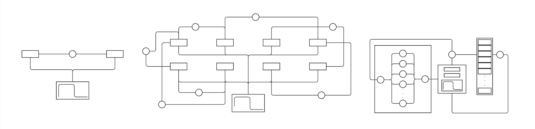
This necessarily segments memory into data memory and instruction memory: memory that represents data and memory that represents the manipulation of data. The fetch-execute cycle describes the life-cycle of data and instruction memory. An instruction is addressed by the address bus and read into the data bus from main memory. This address is stored in the program counter, a register in the control unit, beside an instruction register that will store the instruction on the next edge-triggered clock cycle. Once read into the instruction register the instruction is executed, i.e it is decoded into a set of control signals that indicate the operation to be performed. Useful operations, of which there are many, can be logically grouped. Some such fundamental groups include arithmetic and logical operators, branch and jump operators, and load and store operators. Load and store operators follow from the distinction of main memory registers and core registers. Core registers exist in close proximity to the arithmetic, logic and control units of the architecture, allowing quicker manipulation of data than main memory read-writes allow for. Arithmetic and logic operators act on core register data, and branch and jump operators act on the program counter to move in a non-linear fashion between the subroutines of a program.
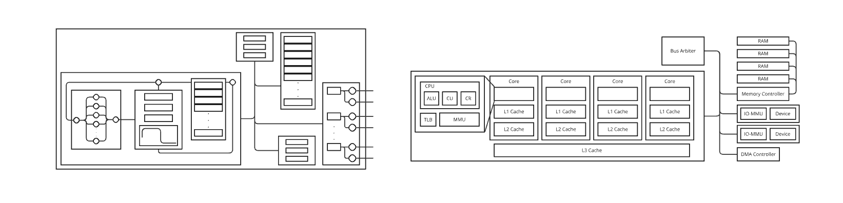
Our computer architecture evolves with the introduction of input and output devices, including a direct-memory-access controller and a bus arbiter to act as additional control units. It is useful to allow direct read-writes between main memory and IO-devices to ensure work can be performed by the core processing unit during IO operations. This is controlled by the DMA controller. The bus arbiter is responsible for arbitrating system bus access between the DMA controller and the core processor. Recall that all such hardware abstractions rest upon data, address and control pathways, allowing for the evolution of state through the processing of a sequence of instructions. These instructions belong to a formal assembly language. Any computer architecture implements some assembly language. Let us use the RISC-V RV32I Base Integer Instruction Set as an introductory example.
Source and destination registers, immediate values, control bits, and opcodes are colored blue, green, yellow and red, respectively. Hundreds of instructions can be expressed by a small number of instruction formats. The R-type (R for register) instruction format has three register bit fields addressing registers in core memory. The control bits tell the core logic unit which operator to apply to these operands before storage. Opcodes put instructions in categories and coordinate the action of hardware components. For example, the opcode for an R-type instruction that loads and stores values to and from core registers will not write-enable main memory, just as the S-formatted STORE instruction will store a value to main memory but not write-enable the core registers.
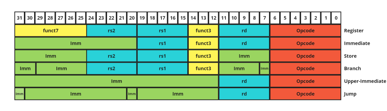
The regular language implemented by the the computer maps to an assembly language. An assembly language is a language with near one-to-one correspondance between instructions and binary. For example, the assembly instruction ADD r1, r2, r3 can be directly fetch-executed and maps to the bit fields \( 0000000 \; 00011 \; 00010 \; 000 \; 00001 \; 0110011\). Further abstractions allow us to move towards the validation and execution of recursively-enumerable languages. These are high-level programming languages far more expressive than assembly. We can start by giving the core registers an additional meaning.
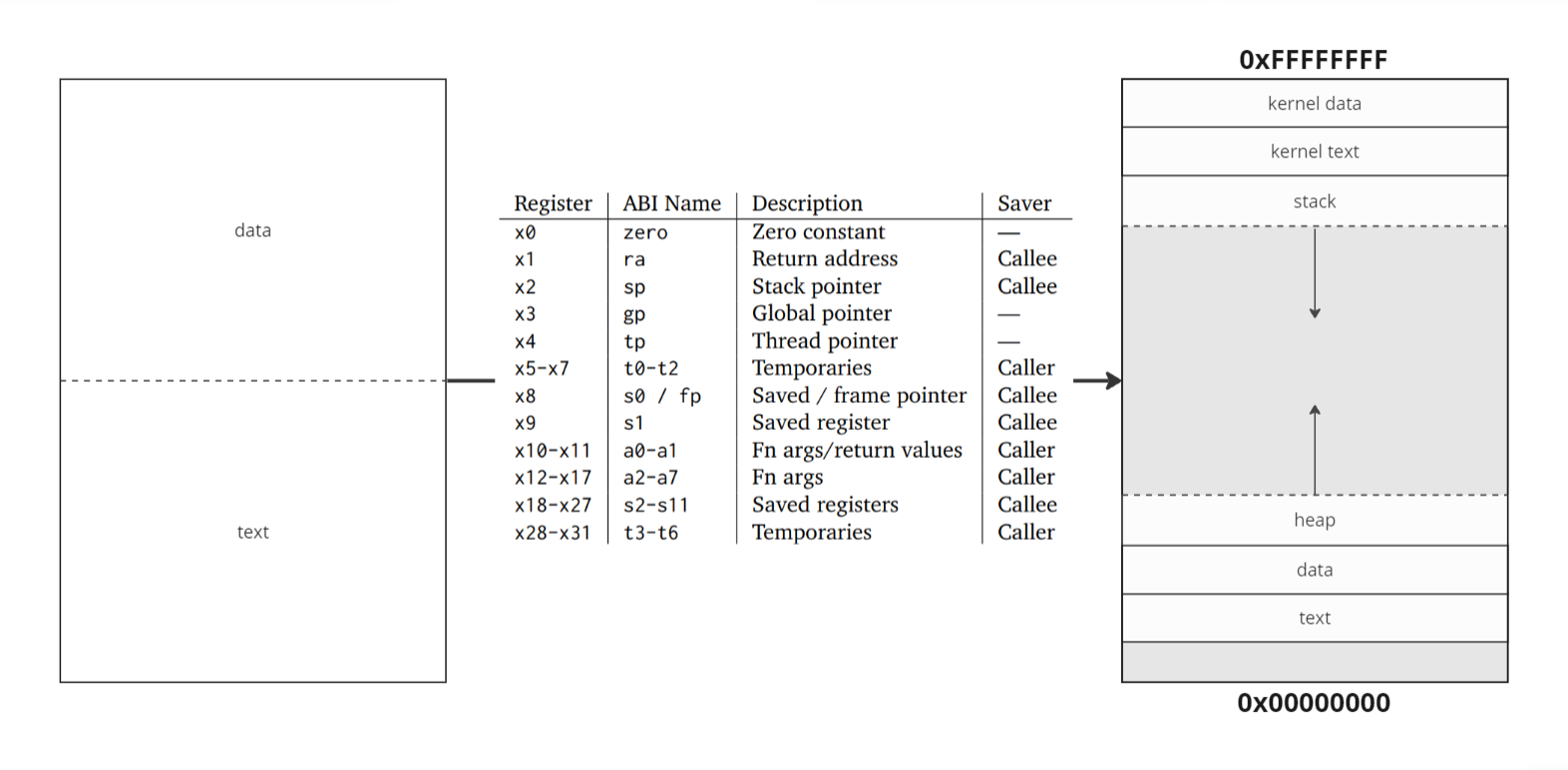
The above register mapping belongs to the RISC-V Instruction Set Architecture, not dissimilar from other ISA register mappings. Register zero is denoted zero in assembly, and is hard-coded with zero bits. It can be used as a constant, and is useful in the creation of pseudo-instructions. For example, 'mv rs rd' could assemble into the equivalent instruction 'add rs rd zero'. The return address register stores the instruction following a function call, so we can return to our current context after a called subroutine has finished executing. Argument registers store arguments or pointers to arguments, which can be accessed by the called function and overwritten with return values. The distinction between temporary and saved registers is that saved registers must be preserved across function calls. To do this, a called function pushes saved register values it wishes to use onto the stack, and then pops them back upon finishing its execution. The stack is accessed by way of a stack pointer. The stack can be thought of as our current context, storing local variables. A function call causes a context-switch. The frame pointer is a pointer to a region of stack memory that preserves important values across function calls. This includes the return address and frame pointer of the caller's context, along with the function arguments it has provided. The caller will have pushed any other values it wishes to preserve, such as temporary register values and function arguments, to its own stack before the context-switch. Saved registers are preserved across function calls. If the callee wishes to use a saved register, it must push the value onto its stack, use the register, and then pop the original value back onto the stack upon completion of its use.
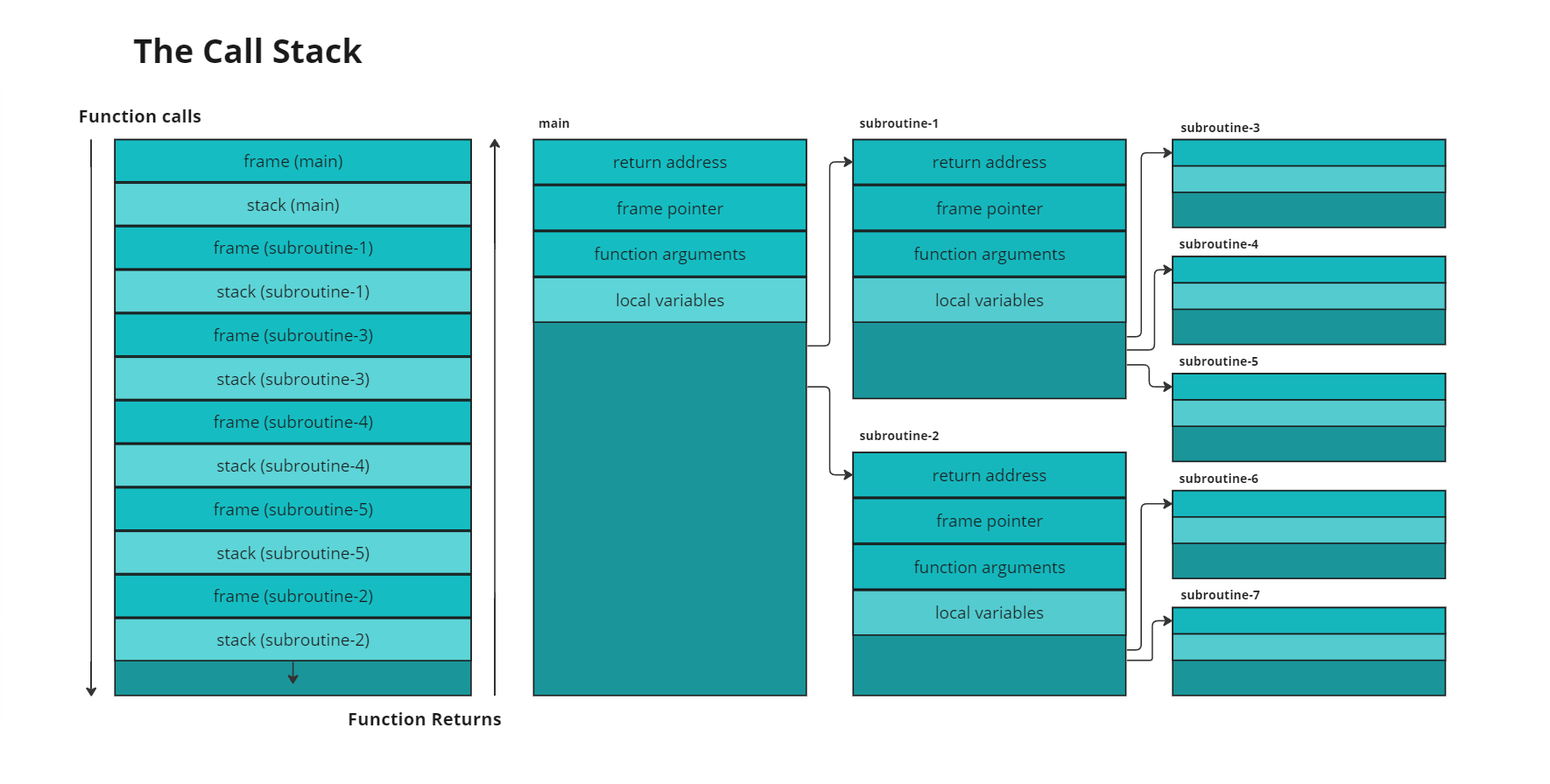
The thread pointer points to thread-local-storage, a region of static data allocated to a thread of execution, and the global pointer points to the data segment itself, which is broken up into two categories, initialised and uninitialised. A hard-coded string literal to be printed to the screen is an example of data stored in the initialised data segment. A string taken from user-input at runtime (with some maximum expected length) is an example of data stored in the uninitialised data segment. Data objects with size determined at runtime are stored on the heap. The user-process loads function arguments and makes a system call to the operating system, which interfaces with I/O devices directly, and manages memory. A successful memory allocation operation will return a pointer to the allocated heap memory. The context that made the system call will store this pointer as a local variable on its stack.
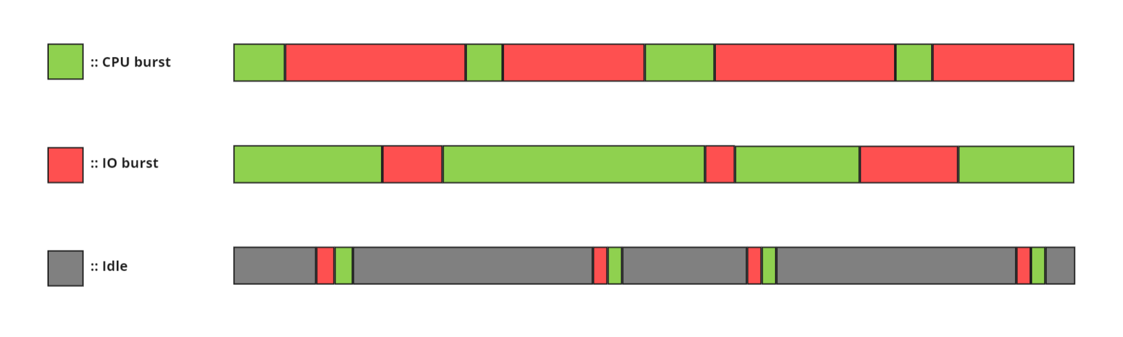
Processes follow this runtime pattern of executing a sequence of instructions, calling a system library, waiting for a response, and then resuming instruction execution. Calls to the system libraries always involve input/output, whether to the operating system directly, to other processes within the same device, or to processes running in external devices via I/O channels. Some processes are CPU-burst heavy, neural network for instance, which occasionally read file training data but are mostly preoccupied with training. Some processes are IO-burst heavy, interactive text editors for instance, which constantly wait for user input. Other processes are idle heavy, automatic update software for instance, which wake after some time period has passed to call servers and check for updates before falling back asleep. Direct Memory Access (DMA) channels are a hardware resource that provide IO devices with direct write-access to main memory. This ensures that the CPU can function simultaneously with large IO data transfers.